We’re currently working on a residential project thick with site complexities and jurisdictional requirements. The lot in question includes an existing home that will be demolished down to the foundation; the majority of the existing foundation will then be retained and reused in the new construction. There are numerous advantages for keeping the foundation; you can read about them here. As typical, the city requires footing drains around the entire perimeter of the house (whether the foundation is existing or new); the relatively small amount of water from these footing drains, along with the much larger quantity of water from the roof downspouts, needs to be managed as part of the building permit submittal. This leaves two options:
1. Tie into the neighborhood’s existing dedicated storm sewer (separate from the sanitary sewer).
2. Engineer the water infiltration on site.
Typically, most projects would tie into the storm sewer and be done with it. But it’s not that easy with this project. As it turns out, the storm sewer is located across the street and would require a complicated (and expensive) process of closing off the street and carefully conducting the necessary work. In addition to this, the nearest catch basin on the storm sewer line sits higher than the existing footing, requiring a pump to properly deliver the water. As our geotech says:
![]() When you need the pump the most is precisely the moment when it won’t work.
When you need the pump the most is precisely the moment when it won’t work.
Meaning that the occasions in which a pump is most necessary are typically the times during extreme weather conditions; the same conditions that commonly knock-out the electricity that powers the pump. Which leaves us with option 2 above; engineering the water run-off so that it properly disperses in the soil on site. He makes a compelling argument.
Working with soil conditions can be a bit perplexing in the architecture world. Some building departments are adamant about bearing capacities, infiltration rates and erosion control methods; other jurisdictions couldn’t care less. There always seem to be inflated factors of safety involved with anything soils related and the publicly available documents on such codes will put you to sleep faster than your dishwasher manual (like King County’s 134 page Surface Water Design Manual Appendix C Small Site Drainage Requirements… yawn). If you’re not careful selecting a professional geotech, it can also seem like hocus-pocus and tarot cards were involved in the soil evaluation process.
Fortunately for us, we work with some good geotechs that keep both feet firmly planted on the ground. We recently met one of our geotechs on site and had a soil evaluation experience that was so straight-forward and productive that we couldn’t help but write about it. Here’s the dirt:
1. The climate and ground conditions were recorded. At the time, it was the worst case scenario for soil drainage as the Pacific Northwest had just received a week’s worth of rain and snow; so the ground was very saturated before we even began testing.
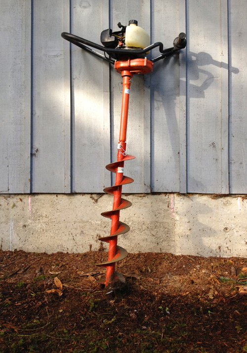
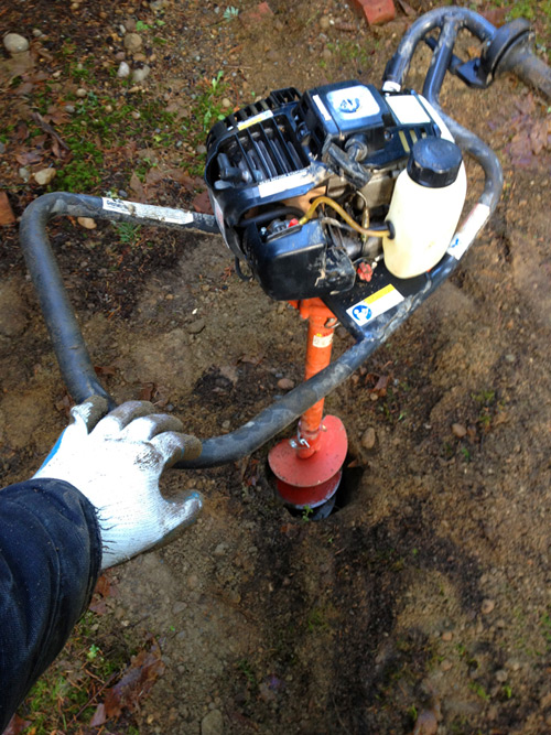
2. We rented a single-man auger post-hole digger (about $50 for 4 hours from Home Depot); this thing is basically a lawn-mower engine hooked up to a really big drill bit.
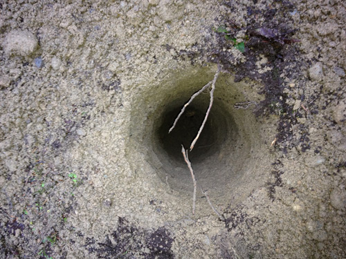
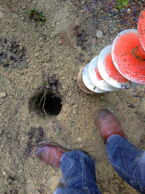
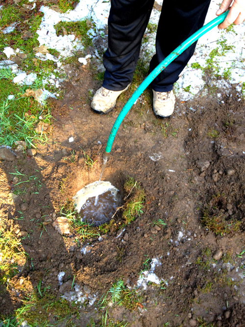
3. (4) 6” Diameter x 3’ deep holes were dug (drilled) on site at a variety of locations to give us the broadest sample of soil conditions on site.
4. The geotech reviewed the soil pulled from the holes and determined that it was excellent for drainage (basically no indications of clay).
5. Each hole was filled with water; the decrease of water level was then measured per minute. We found that the water decreased an average of 2” per minute. According to our geotech, a rate of 10” per hour is good -so the soil on site is exceptionally well draining (even in the wettest of weather conditions).
6. The hole locations and findings were recorded on our site plan for future submittal to the building department.
7. Using section C.2.2.3 “USE OF GRAVEL FILLED TRENCHES FOR FULL INFILTRATION” of the King County’s 134 page Surface Water Design Manual Appendix C Small Site Drainage Requirements (yawn), our geotech applied the guidelines of 20 linear feet of trench per 1,000 square feet of impervious surface on site. These trenches should be 2 feet deep by 2 feet wide and filled with ¾” to 1 ½” drain rock; this drain rock can remain exposed or covered with backfill. A 6” diameter perforated PVC pipe should be embedded within the trench.
8. Using our maximum impervious area of 3,000 square feet we came up with 80 linear feet of trench or (2) 40 foot trenches.
9. The geotech will email us his recommended details sketched out; we’ll draft them up and incorporate them with the permit set. We’ll update the plans with the appropriate drainage trench information.
10. Once the permit set is produced we’ll send the geotech a copy to sign, stamp and bless; we’ll combine this set with a letter from the geotech stating his findings and submit with the permit set.
You can, of course, have a full-service geotech crew handle the entire package, but it can get a bit expensive and occasionally time consuming. The method described above worked on this particular project because it was cost-effective, straight-forward and gave us a quick turn around on the answers we needed. And this experience is aligned with our lean approach to creating projects that are only as expensive as they must be.
We should really give out a free lunch or something for anyone who makes it through a post on soil infiltration, eh?
Cheers from team BUILD


